In order to improve my calculator emulator, I am reverse-engineering a TI-30Xa. I want to be able to send key presses electrically from a microcontroller. This requires knowing the layout of the keypad matrix, i.e. what wires connect to what buttons. Unfortunately, the circuit board is riveted down with plastic. I don't have direct access to the far side of the circuit board because I want to keep the calculator in a working state.
There are a couple ways I could still get access to the other side of the circuit board.
-
I could get the thing x-rayed. That would be expensive. It would be way more cost-effective to just buy another calculator to disassemble.
-
I could drill out the rivets and replace them with appropriate screws. I'm not sure if the right screws would be a common size, so this might also get expensive. Besides, I would rather not have to take the thing apart again.
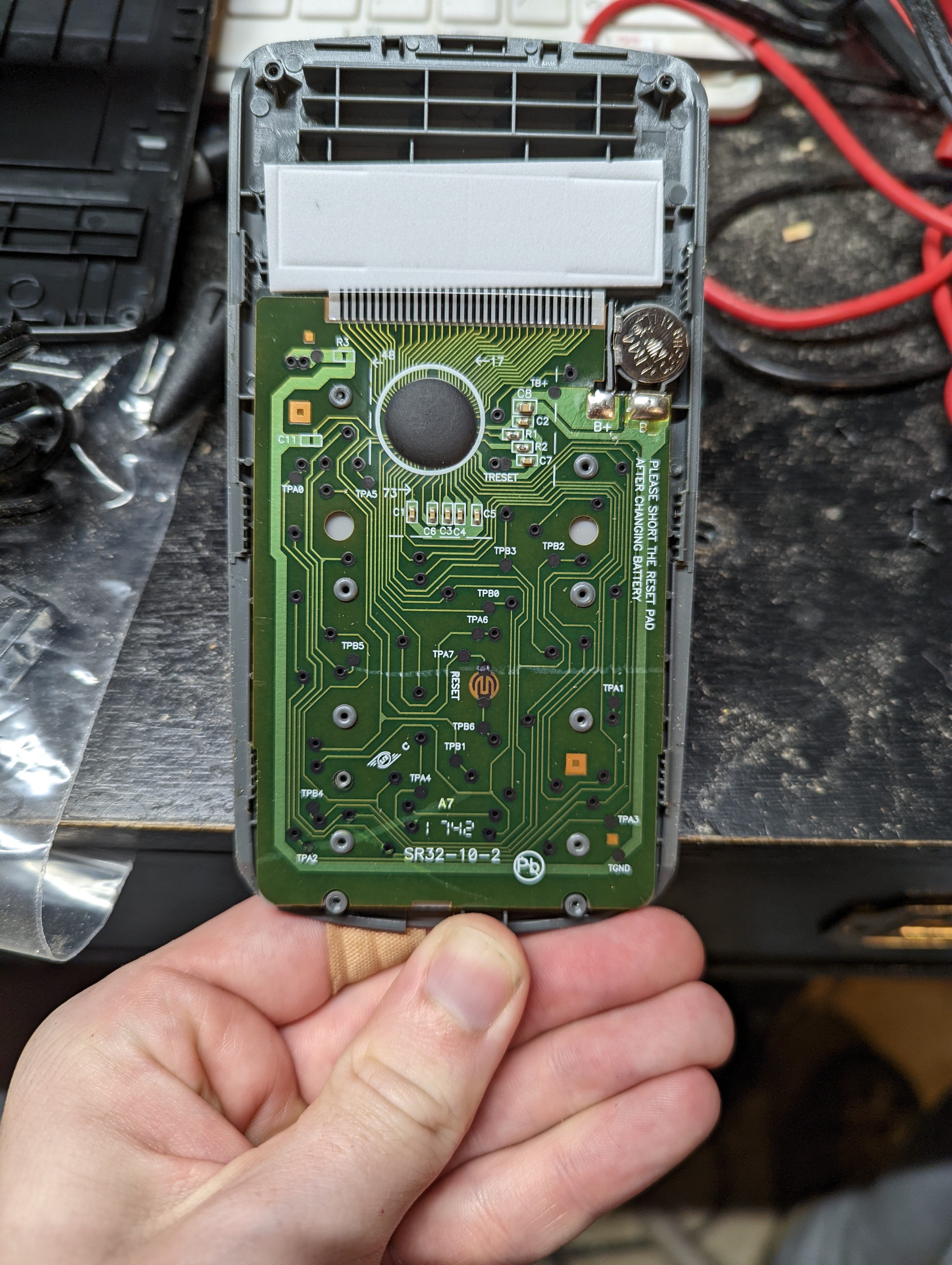
Instead, I used an indirect method. Since I have electrical access to all the test points, I can just connect an ohmmeter between an A wire and a B wire, then look for a button press which changes the measured resistance. In theory there should be one button for every pair of wires in the matrix.
Here is the result, after measuring every pair.
| A0 | A1 | A2 | A3 | A4 | A5 | A6 | |
|---|---|---|---|---|---|---|---|
| B0 | +/- | 2nd | + | 0 | . | SIN | 1/x |
| B1 | y^x | HYP | - | 1 | 5 | COS | x^2 |
| B2 | OFF | pi | X | 2 | 6 | TAN | sqrt |
| B3 | Sigma+ | / | 3 | 7 | DRG | EE | |
| B4 | STO | = | 4 | 8 | LOG | ( | |
| B5 | RCL | ab/c | <- | 9 | LN | ) |
There are a few things about this layout that surprised me.
-
There are only 39 of the 40 keys represented here, even though there are three unused connections in the A0 spot. Further probing shows that the ON key pulls the RESET pin to ground, which we can see from the visible traces has an external pullup to B+. It makes sense in retrospect that ON would have its own pin, since they would want to activate it from an interrupt, not with the active polling that a matrix keypad requires.
-
B6 and A7 don't seem to be connected to the rest of the matrix. We can see on the circuit board that they are connected to either side of the RESET pad, which (if we believe what's written on the board) should put the calculator in a stable state after power loss. It's strange that this would use two pins, when the same effect could be done with a pullup and a ground. Perhaps this has something to do with wanting the RESET pad to work even if the calculator is in an off state, so that whoever is changing the battery does not need to turn the board over while it is disassembled. I don't have an explanation, it is still a mystery to me.
Since each key has two coordinates which range from 0 to 7, it seems natural to represent each key with a single byte. Three bits for A, three bits for B. That leaves two bits left over, which could be used to signal the special values ON and RESET, though of course we could also use them for something else, since we have so many of the 64 places in the table unoccupied. I am getting ahead of myself here.
Now that I know a bit more about what the wires on this calculator do, it is interesting to compare a previous revision which I have also photographed but have not probed.
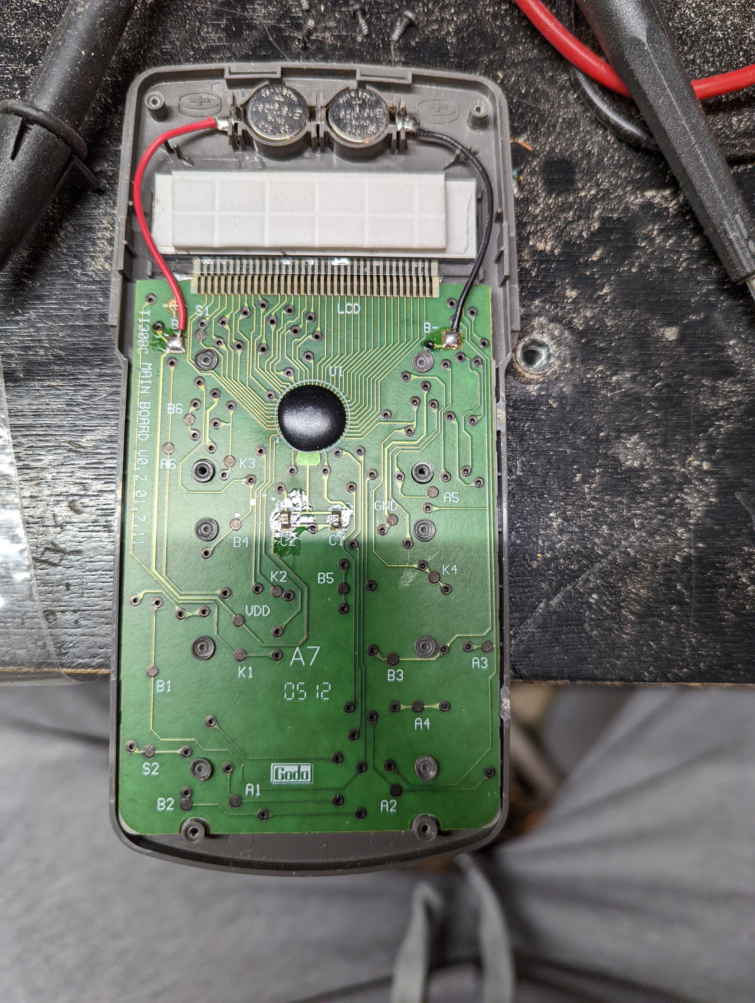
A few differences are obvious -- it runs at 3 volts instead of 1.5, all the soldering was done by hand, there are six screws instead of four. If you look at the display from the front you can see it has all the same segments, though they are a bit smaller and slightly different in shape. It also has 32 wires going to the LCD, so I imagine it is driving them in the same 28x4 manner. Some of the LCD wires are also going elsewhere using vias, for example you can see S2 in the lower left. What's it doing there? Are some of the LCD wires doubling as keypad timing signals? There are only seven traces leading to the microcontroller which don't also touch the LCD, so I suppose it must be using those 15 LCD wires with vias to poll buttons some of the time.
We have the familiar A1 through A6 and B1 though B6, though no A0 or B0 so I expect they are counting from 1 in this model. There is a big A7 printed in the middle, but it doesn't seem to be associated with any one trace or pad. Most puzzling of all are the pads labeled K1 through K4. What could they be doing? Maybe in this version only 36 of the buttons are in a matrix, and the other four use pads K1 through K4.
Those questions will have to wait for another day. For now it is enough to see that in the modern revision we now have a correspondence between traces and buttons, without having to disassemble it any further.