This past weekend I sat down to solder some connectors onto a TI-30Xa calculator, which will be used in an upcoming project to validate the emulator I have written. This stirred up some thoughts which might be helpful to anyone who is beginning in electronics, as I once was. In no particular order, I will share those thoughts here.
Why use connectors?
The most direct way to get electrical access to a circuit is with probes -- the pointy things which come with most multimeters or oscilloscopes. In fact, that's what I used at first, to begin understanding the circuit I am dealing with. Looking at the circuit board before modification, we can see some handy labeled test points. Those are the black circles without holes in them.
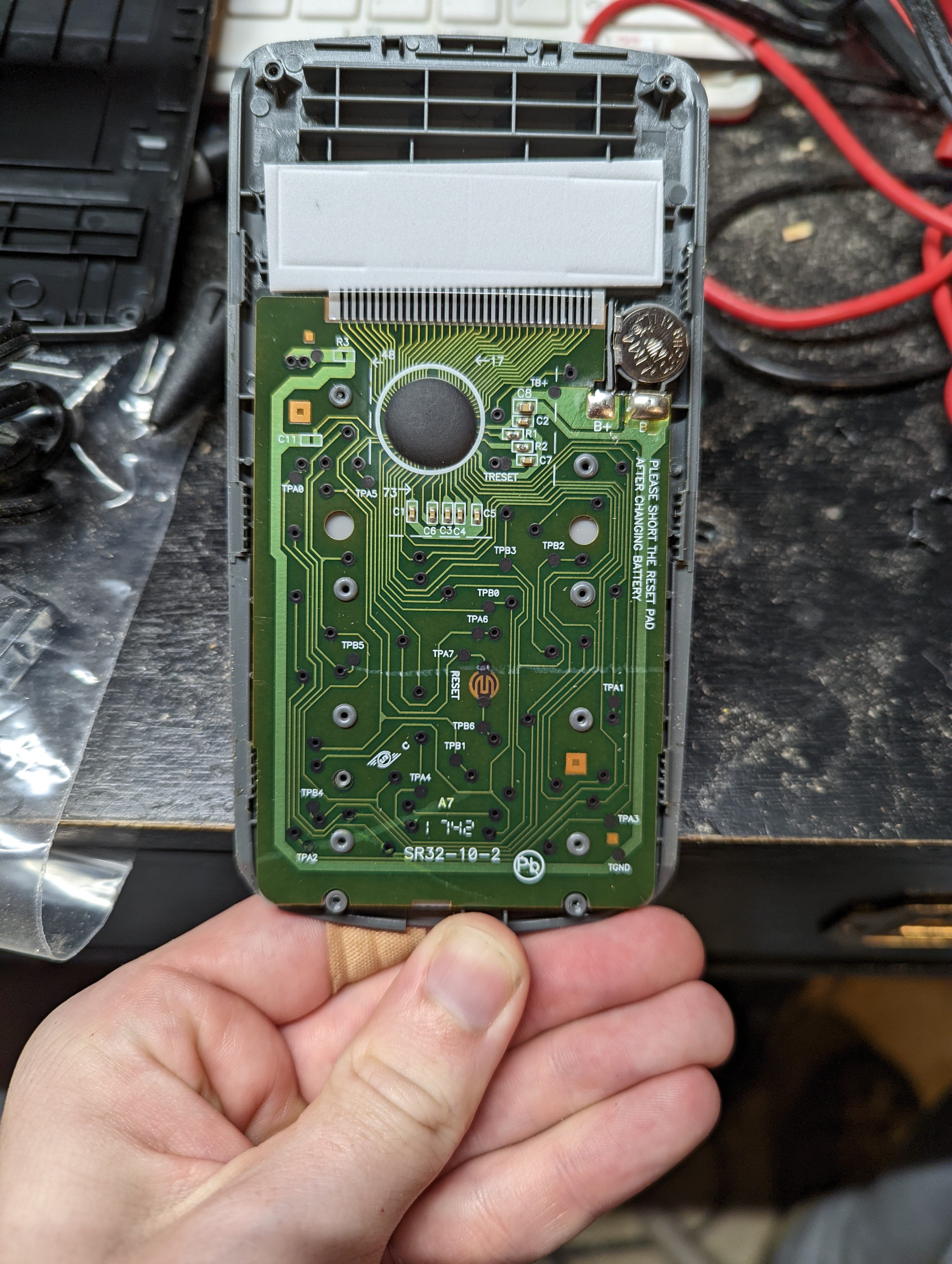
You can also see the same black material up at the top, where the ribbon for the LCD is glued on. This material is electrically conductive, so we can just push a probe into it to find the signal we wish to measure.
That's all well and good for measuring one or two pins at a time. It is not so good for measuring several at once, and it is not good for making a permanent connection. Instead, we should solder onto the circuit to make the connection permanent. The most obvious way to do this would be to split apart one (or multiple) ribbon cables and leave them running out of the calculator, ready to wire onto a circuit board at the far end. I considered this. I decided against it for a few reasons, and it turned out to be a good decision.
Separation of concerns
A ribbon cable would require making every connection right on the first try. If I can use a separate wire for each connection then I have the freedom to throw it out if I make a mistake, make each connection the perfect length, and rework after the fact if I decide to change just one part. All of that would be near impossible if I were using one big ribbon cable, since all the wires used in soldering would be fused together. Also, I don't even want to think about the nightmare of keeping a bunch of loose wires in order running out of the calculator directly. The connector allows me to separate my concerns, letting me separately use the best wires for inside the calculator and for outside the calculator, without having to compromise.
Modularity
This project is an infant. I don't know what kind of circuit will be at the other end of the wires just yet -- which ones should go where? By using a connector I can easily build a simple test setup now, and replace the whole thing later once I know the permanent solution.
Reuse
In the future, I may want to repurpose this part for something else -- maybe a version of the calculator which connects to a display for projection, for example. Also, there is no reason why I should not allow it to still function as a pocket calculator. Those would be much harder to do in the future if I have a bulky bundle of wires hanging out of it. By using connectors I free myself up to do different things in the future without having to modify the calculator even further.
Choice of connector
The calculator has 32 pins going to the display, 15 for the keypad, one labeled "reset", and two battery connections. That makes 50 connections in all which I want to be able to access from the outside. What connector could be appropriate?
I have grown to like IDC connectors from prototyping, since they have the 0.1 inch pin spacing that most prototyping boards share and they are keyed preventing reverse insertion. The obvious choice for this project would be a 50 pin IDC cable, but I discarded this option for two reasons:
-
While the cables are readily available since they are used for 8-bit SCSI drives, the headers are not so easy to come by.
-
The calculator is just a bit narrower than the 50 pin header is long. Using this connector would threaten the structural integrity of the case.
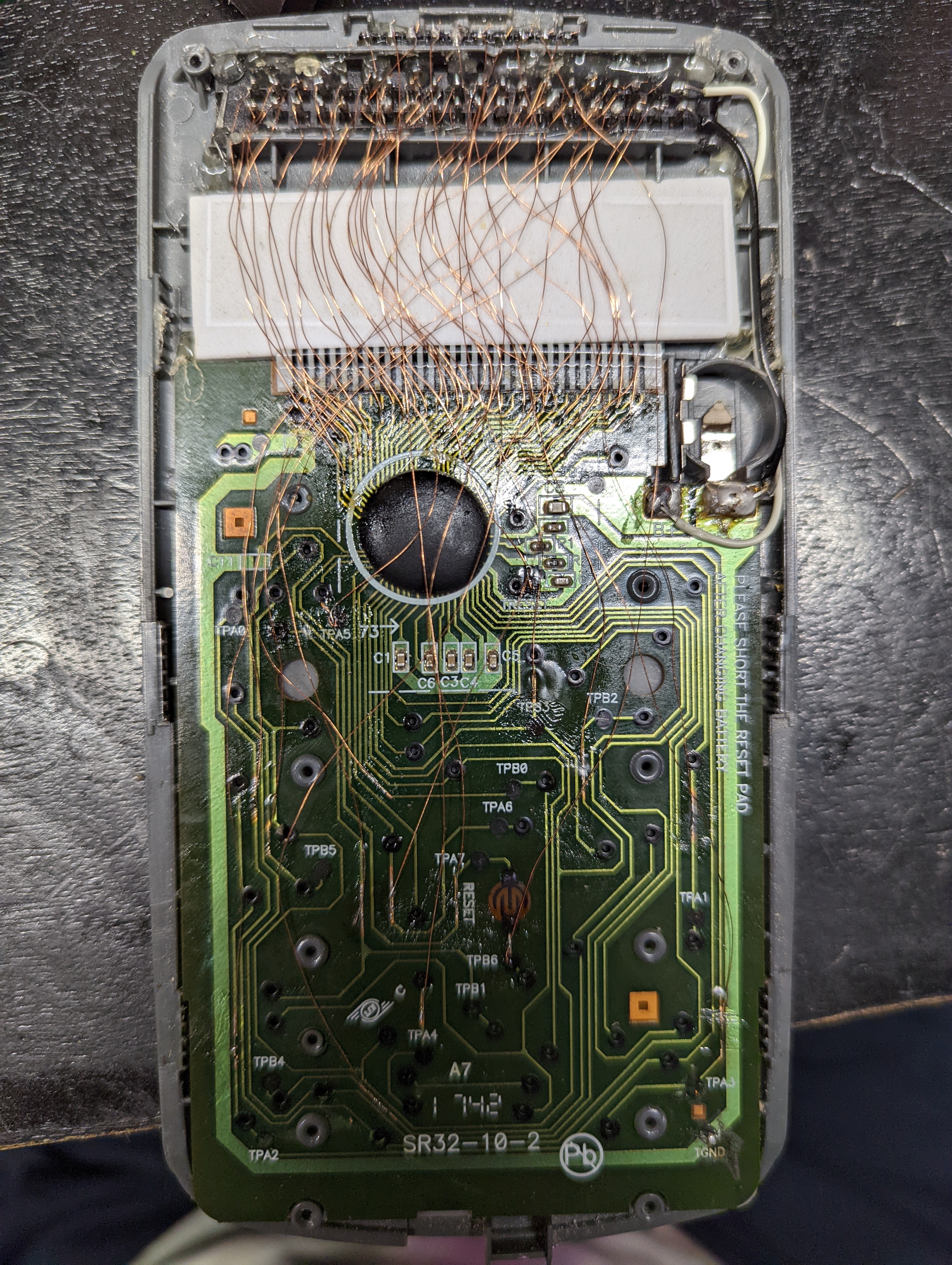
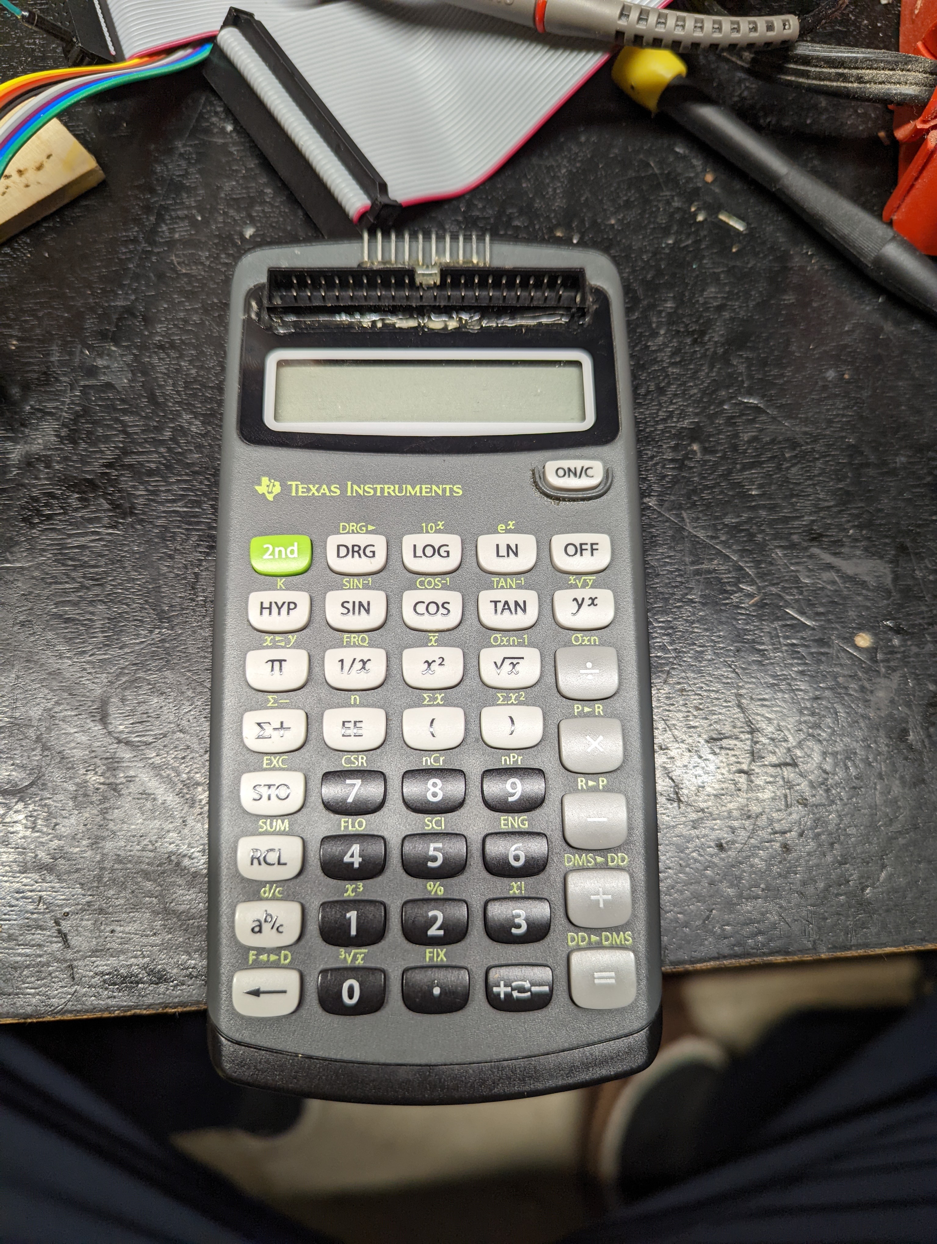
I opted to use a 40 pin IDC cable, which fits nicely in the space where a solar panel would go in the school edition of the calculator. These headers and cables are also much cheaper. The down side is that I need to find a space for ten more pins. There is a common 10 pin IDC cable, but there is not enough room in the calculator for it. Two more rows of pins would spill over the top of the calculator. There is a 10 pin JST connector available which is keyed and has all 10 pins in a single row, but it is expensive in small quantities. That's why for these 10 additional pins I chose to just use a row of bare headers affixed to the case with hot glue. Not perfectly elegant, but compact and flexible enough for this project. Here you can see how it all fit together, inside and out.
If I had an unlimited budget, I think the best solution would be a DB50 D-sub connector. Since these put the pins in three offset rows they can be a lot more compact, and they are available in panel mount configurations so we could get a secure connection to the calculator case. They strike a good balance between being small enough to fit the space I have and large enough to still be able to solder individual wires. At $10 a connector and $30 a cable, the price is too much.
Because it would be unpleasant to have to trace out all the connections I just made by hand, I will relay them here in a table. Here is what each pin connects to, as viewed from the outside.
| - | - | - | - | - | RESET | B6 | B5 | B4 | B3 | A7 | A6 | A5 | A4 | A3 | - | - | - | - | - |
|---|---|---|---|---|---|---|---|---|---|---|---|---|---|---|---|---|---|---|---|
| B+ | B2 | B1 | B0 | 1 | 3 | 5 | 7 | 9 | 11 | 13 | 15 | 17 | 19 | 21 | 23 | 25 | 27 | 29 | 31 |
| GND | A2 | A1 | A0 | 2 | 4 | 6 | 8 | 10 | 12 | 14 | 16 | 18 | 20 | 22 | 24 | 26 | 28 | 30 | 32 |
B0 through B6 and A0 through A7 are the traces for the keypad matrix, matching the labels on the test pads. I have also copied the labels on the test pads for B+, GND, and RESET. I have chosen to number the traces going to the LCD in increasing order, starting from the trace nearest to the battery.
Notice I also removed the battery. The calculator would still work with the battery, and I could even read values from it with the battery installed. It would save me from having to make an external 1.5 volt source. I chose to remove the battery because it is a pain to open the calculator up, even more so now that there is delicate wiring throughout. If I left the battery in, one day I would have to open this up again to remove it, because dead batteries can leak. It is better to power it externally for the duration of this project. If in the future I want to use this as a normal calculator again then I can simply put the battery back in.
Soldering thoughts
I am not sure what the black conductive coating on the test points in this circuit are. In most circuit boards the test points and through holes are plated with a zinc alloy to make it easier to solder onto them. This board has no through hole components, so I am guessing they skipped the plating step altogether. I am guessing the coating they used is ideal for the membrane keypad on the other side of the circuit board.
Unfortunately for me, that black coating is not solderable. That means I have to solder onto bare copper. Here are some things I figured out along the way.
Flux is mandatory
The flux in the core of my solder was not nearly enough. I was able to get a connection one or two times, but the repeated heating and cooling from several solder attempts caused the copper to corrode making it impossible to connect in some places. I even broke one of the traces at one point from scraping away the corrosion too many times, which I then had to repair. These problems went away when I started using some cheap paste solder. I was able to get a good connection on the first try most of the time using flux.
Match the size of the wire to the trace
It became much easier to solder onto the traces when i started using magnet wire instead of the random scraps of wire I had laying around. It is slightly thinner than the traces I was soldering onto. This made the whole space less crowded which made it easier to make a connection without damaging a previous connection. The magnet wire was also better matched to the thermal mass of the trace, so they heated at a similar rate which made the soldering go quicker.
Mechanical contact precedes thermal contact
The soldering iron has to get the soldering surfaces hot, and it does that by touching them. If there is not much pressure between the iron and the soldering surface, heat will flow slowly. This is a particular challenge for the magnet wire, as it does not resist bending at all. In order to tin the wire, I got a scrap of wood and pressed the wire down onto it using the soldering iron. This probably also helped in scraping the insulation from the end of the wire. Doing it this way I was able to tin the end of the magnet wire quickly and reliably.
My test setup
On a project with so many parts I am bound to get confused at some point, and things are bound to not work on the first try. This means it is extra important that I always know what parts are working and what parts are not. I don't want to be debugging this circuit a month down the line to find that my problems are from a bad solder joint that went undetected. That why before and after every solder connection I tested the circuit to make sure the signal from each trace made it to its designated pin. This would get tedious if I had to put in and remove the battery every time -- I could even have damaged the battery connector doing that. Instead, I got out an LM317 voltage regulator and powered the calculator from a bench power supply. By wiring a switch in line, I could easily engage or disengage power as needed without putting wear on the calculator itself.
Before making each solder connection I probed the trace to see what signal was there. These are low frequency signals, changing on the order of 100 Hz, so it was not essential to have the oscilloscope probe grounded directly to the board -- grounding to the power supply was perfectly adequate. Once I knew the shape of signal, I could turn off the calculator with the switch, solder the wire to the connector, turn it back on, and look for the signal on the output pin. This caught faulty connections several times, which saved me the effort of going back to previous work after having already moved on.
I could have done this a more basic way, just setting my multimeter to continuity mode and probing a couple points each time, maybe checking the signals at the end using the battery. That would have been quicker to set up since all it would take would be removing the battery. The method I chose was slightly faster to use, since I only needed one hand for the oscilloscope probe. I also got a more direct confirmation that the entire path from the LCD driver to the output pin was intact. By investing a bit of time in the setup, I was able to save a lot of time during the tedious portion of the operation. This is a general principle: it's better to take the time to find a good way to do a repeated task, rather than diving in to the method with the fastest setup time.
Conclusion
Part of the joy of this hobby is finding small ways to optimize, finding a cheap solution which is still reliable and doesn't need too much labor. We got to experience some of that in picking out the connectors and wires, and ensuring reliability by testing at every stage. Another source of joy is in taking a complicated system and exploring it until you know all there is to know about it. We had to do some of that exploring here to make sure we are extracting the right test points, but mostly the wiring done here will enable us to explore the rest more easily in the future. This is a slow hobby, where we are constantly laying the groundwork for what is to come. If we already understood the circuit and knew how we would interface with it, we could jump straight to the end and print a PCB that handles most of this for us. That would also remove all of the fun, at least from my point of view.